Introduction
Sensors and Mixed Signal devices will require trimming of internal circuit during evaluation and mass production. You can do such trimming easily by using CloudTesting™ Service.
As “the use case of Pattern Modify IP and loop control function of CloudTesting™ Lab Expert Mode” in the supplemental of Trimming, this document explains the circuit adjustment of target devices by motifing a psuedo device.
Correction example of comparator comparative voltage(offset)
Psuedo device specfications
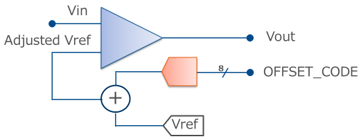
- When the voltage of the input signal to the comparator circuit exceeds the comparison voltage, the detection signal changes from Low Level to High Level.
- In order to adjust the individual difference of the comparison voltage of the comparator circuit, input the voltage obtained by adding the voltage of the adjusting offset voltage generating DAC to the Vref voltage.
- The adjustment circuit has a 1-byte register, and the comparison voltage can be adjusted by writing data to the register.
- Register read / write of the adjustment circuit can be accessed from the parallel I/F.
Program flow
Details of sample programs
| Test number | Test name | Algorithm name | Notes |
|---|---|---|---|
| 0 | FUNCTIONAL TEST | Functional Testing IP | Perform Go / No-Go judgment of the detection signal. |
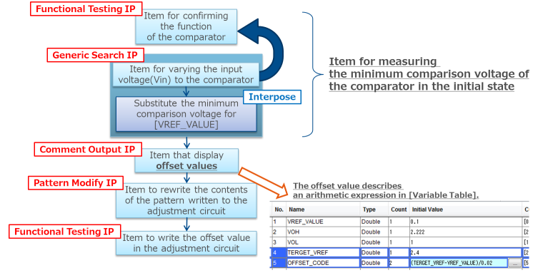
| 1000 | VREF min TEST | Generic Search IP | Search for the minimum comparison voltage. |
| 1001 | PRINT OFFSET_CODE | Comment Output IP | Display the offset value for the adjustment circuit on the console. |
| 1002 | UPDATE OFFSET PAT | Pattern Modify IP | Rewrite the pattern applied to the adjustment circuit. |
| 1003 | ADJUST VREF OFFSET | Functional Testing IP | Write the offset value to the adjustment circuit. |
Supplement
- The input voltage value to the comparator is specified by the variable [VREF_VALUE].
- Change the value of the variable [VREF_VALUE] to find the minimum comparison voltage.
- Based on the minimum comparison voltage, convert it to data for the adjustment circuit and store it in the variable [OFFSET_CODE]. This conversion (calculation) is automatically done by defining an arithmetic expression in [Variable Table].
- The test pattern data is rewritten using the value of the variable [OFFSET_CODE].
- By the test pattern is rewritten, it writes to the adjustment circuit of the device.
Adjustment example of variable resistor
Psuedo device specfications
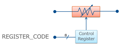
- The variable resistor has 1 byte register, and the resistance value changes by writing data to the register.
- Register read / write of the register can be accessed from the parallel I/F.
Program flow
Details of sample programs
| Test number | Test name | Algorithm name | Notes |
|---|---|---|---|
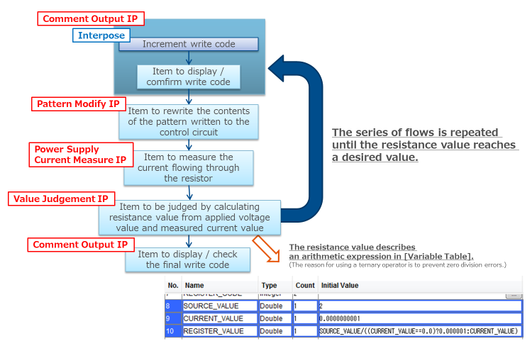
| 2000 | PRINT REGISTER CODE | Comment Output IP | Display the code that sets to the variable resistor to the console. |
| 2001 | UPDATE REGISTER PAT | Pattern Modify IP | Rewrite the pattern accessing the variable resistor. |
| 2002 | CURRENT MEASURE | Power Supply Current Measure IP | Measure the current flowing through the resistance. |
| 2003 | REGISTER TEST | Value Judgement IP | Judge the resistance value obtained from the applied voltage value and current value. |
| 2004 | PRINT FINAL REGISTER CODE | Comment Output IP | Display the code set in the variable resistor to the console. |
Supplement
- The code that determines the resistance value is specified by the variable [REGISTER_CODE].
- Rewrite the test pattern data using the value of the variable [REGISTER_CODE].
- By the test pattern is rewritten, it writes to the variable resistor.
- Repeat 2000 - 2003 until the 2003 REGISTER TEST PASSes.
- Repeat execution control is performed by Flow branch control.
- The value of the variable [REGSTER_CODE] is the same as the number of iterations(=System variable [SYSMeasureItemExecuteCount]).
Adjustment example of reference voltage circuit (binary search)
Psuedo device specfications
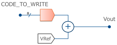
- The output voltage value of the reference voltage circuit has individual differences and there is an adjustment circuit for correcting it.
- The adjustment circuit has a 1-byte register, and by writing data to the register, the output voltage can be adjusted.
- Register read / write of the adjustment circuit can be accessed from the parallel I/F.
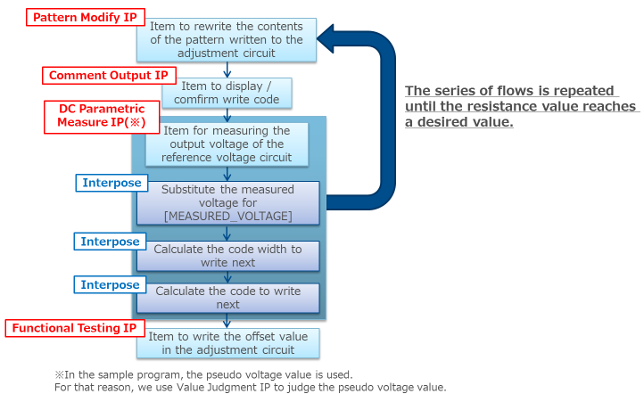
Program flow
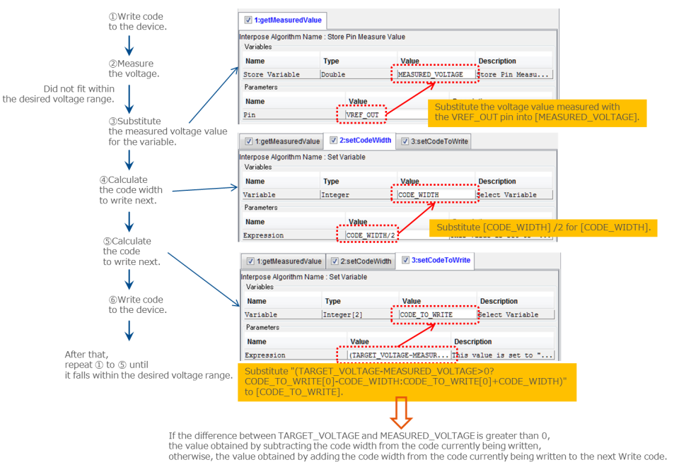
Explanation for Interpose
Details of sample programs
| Test number | Test name | Algorithm name | Notes |
|---|---|---|---|
| 3000 | WRITE CODE | Pattern Modify IP | Rewrite the contents of the pattern written to the adjustment circuit. |
| 3001 | PRINT CURRENT CODE | Comment Output IP | Display the code to be written on the console. |
| 3002 | VOLTAGE MEASUREMENT | DC Parametric Measure IP | Write the code and measure the voltage. * In the sample program, the pseudo voltage value is used. For that reason, we use Value Judgment IP to judge the pseudo voltage value. |
| 3003 | WRITE CODE(FINAL) | Functional Testing IP | Write the adjusted code. |
Supplement
- The code that determines the adjustment value is specified by the variable [CODE_TO_WRITE].
- Rewrite the test pattern data using the value of the variable [CODE_TO_WRITE].
- By the test pattern is rewritten, it writes to the adjustment circuit of the device.
- Repeat 3000 - 3002 until the 3002 VOLTAGE MEASUREMENT PASSes.
- Find the optimized code by binary search.
Application example
- Generic Search IP can be used not only for Go/No-Go judgment by Functional Testing IP but also for measurement IP using Power Supply, PMU, Digitizer, Counter.
- Parameters that can use arithmetic expressions (such as [Variable Table] and Interpose) allow not only arithmetic operations and bit operations but also arithmetic operations using the ternary operator and the Java Math class.
- More complicated operations can be realized by making an Interpose algorithm by yourself.
- Linking with external tools can be done by Batch File Execution IP.
Download for sample programs
Please download from here.
To download a sample program requires membership registration.
If you are not already registered as a member, please register as a member from here.
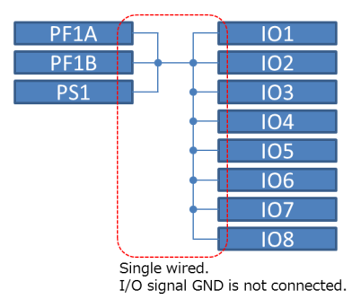
Pseudo device circuit example
The sample program of “Correction example of comparator comparative voltage(offset)” and “Adjustment example of variable resistor” operates with the following circuit.
If you want to run these sample programs, please wiring in accordance with the following circuit example.
Note that the sample program of “Adjustment example of reference voltage circuit (binary search)” does not require a pseudo device circuit.
PLEASE READ CAREFULLY
NOTICE : ADVANTEST CORPORATION (“ATJ”) PROVIDE THIS DOCUMENT, WITH FREE OF CHARGE, AS A REFERENCE FOR CUSTOMER(S) TO PREPARE ITS ORIGINAL SOFTWARE AND CIRCUIT USED IN CONNECTION WITH THE SUBSCRIPTION OF ATJ’ SERVICE. CUSTOMER MAY DUPLICATE OR MODIFY SAMPLE PROGRAM AND CIRCUIT EXAMPLE IN THIS DOCUMENT OR ATTACHED SAMPLE PROGRAM AND CIRCUIT EXAMPLE; HOWEVER, ADVANTEST CORPORATION DO NOT GUARANTEE THAT ANY KIND OF FUNCTIONAL CONFORMITY AND/OR MALFUNCTION AND/OR ANY DAMAGES INCURRED DUE TO THE USE, OF THIS SAMPLE PROGRAM AND CIRCUIT EXAMPLE AND/OR ITS DERIVATIVE SOFTWARE AND CIRCUIT. ADVANTEST CORPORATION DEEM THAT THE CUSTOMER(S) RECOGNIZED AND AGREED TO THE TERMS OF USE SHOWN ABOVE WHEN CUSTOMER(S) RECEIVED THIS DOCUMENT OR ATTACHED SAMPLE PROGRAM AND CIRCUIT EXAMPLE.